Online Flyback RC Snubber Calculator

Calculate snubber components to reduce ringing and improve EMC performance

Biricha Flyback Snubber Design Tool

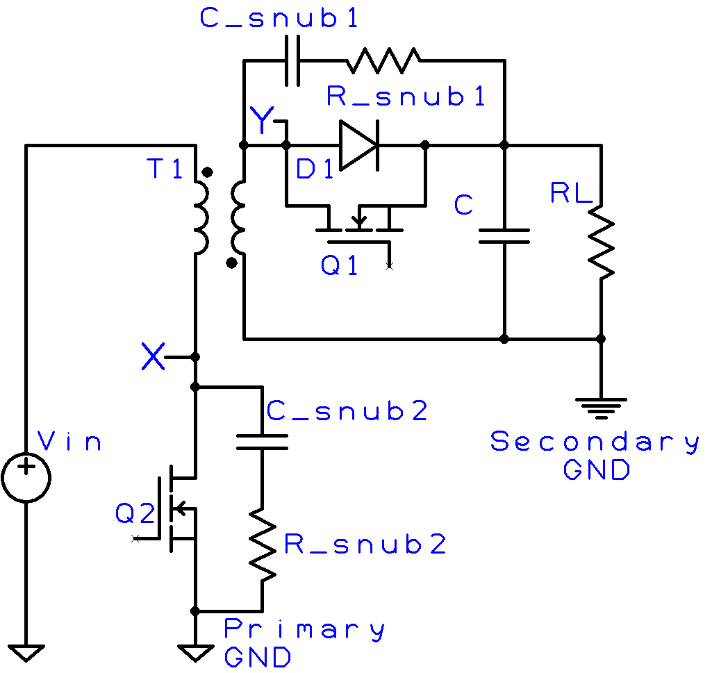
Enter the required parameters and this online calculator will calculate the snubber R and C values for the Flyback converter.

V
to 1
e.g. if your transformer has a turns ratio of 3 to 2, type in 1.5 and the tool will do the rest
V
V
Hz
e.g for 100kHz you can type 100000 or 100e3

Low Side Switch (Q2) Snubber Calculations (R_snub2 & C_snub2)
Hz
e.g. for 27MHz you can type 27e6. Note: measure with respect to primary ground.
W
e.g. for 50mW please type in 50e-3
For reference typical maximum dissipation for 1 oz FR4 PCB with minimal pad size (check manufacturer datasheet) 1206 package ~ 0.125W to 0.250W 1210 package ~ 0.25W to 0.500W
F
Select a capacitor value close to this. After selecting this first pass snubber capacitor value solder this capacitor in place of C_snub2 and temporarily short R_snub2 with a 0R resistor. Then please follow the instructions below.
F
e.g. for 400pF please type in 400e-12
Note: If snubber capacitance is too big, power dissipation will be large; if it is too small the circuit will not work well This power will be lost when you solder a snubber resistor.
W
Hz
F
H
ohms
Note 1: Use as close a value as possible Note 2: To finalize your design, look at the ringing again. Ideally there should be only 1 or no undershoot. If this is the case, you may be able to reduce C_snub2 and check to see if you can reduce your losses
Secondary Side Switch (Q1/D1) Snubber Calculations (R_snub1 & C_snub1) Note: Often you do not need this after soldering the primary side snubber. Make sure the primary side snubber is in the circuit and functioning before adding this secondary side snubber.
Hz
e.g. for 90MHz you can type 90e6. Note: measure with respect to secondary ground.
W
e.g. for 50mW please type in 50e-3
For reference typical maximum dissipation for 1 oz FR4 PCB with minimal pad size (check manufacturer datasheet) 1206 package ~ 0.125W to 0.250W 1210 package ~ 0.25W to 0.500W
F
Select a capacitor value close to this. After selecting this first pass snubber capacitor value solder this capacitor in place of C_snub1 and temporarily short R_snub1 with a 0R resistor. Then please follow the instructions below.
F
Note: If snubber capacitance is too big, power dissipation will be large; if it is too small the circuit will not work well This power will be lost when you solder a snubber resistor.
W
Hz
F
H
ohms
Note 1: Use as close a value as possible Note 2: To finalize your design, look at the ringing again. Ideally there should be only 1 or no undershoot. If this is the case, you may be able to reduce C_snub2 and check to see if you can reduce your losses
Your design is complete! 🙂

Register to receive invitations to our workshops